Draw Entity Relationship Diagram Boxes in Java
Entity-Relationship Diagrams
ER-modeling is a information modeling method used in software applied science to produce a conceptual information model of an information system. Diagrams created using this ER-modeling method are called Entity-Relationship Diagrams or ER diagrams or ERDs.
Purpose of ERD
- The database analyst gains a better understanding of the data to be contained in the database through the pace of constructing the ERD.
- The ERD serves as a documentation tool.
- Finally, the ERD is used to connect the logical construction of the database to users. In particular, the ERD effectively communicates the logic of the database to users.
Components of an ER Diagrams
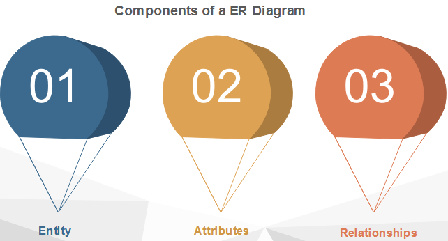
1. Entity
An entity can be a real-earth object, either animate or inanimate, that tin exist but identifiable. An entity is denoted equally a rectangle in an ER diagram. For example, in a school database, students, teachers, classes, and courses offered can be treated as entities. All these entities have some attributes or properties that requite them their identity.
Entity Set
An entity set is a collection of related types of entities. An entity set may include entities with attribute sharing similar values. For example, a Educatee set may contain all the students of a school; likewise, a Teacher set may include all the teachers of a schoolhouse from all faculties. Entity set need not exist disjoint.

2. Attributes
Entities are denoted utilizing their backdrop, known as attributes. All attributes have values. For case, a educatee entity may have proper name, class, and age every bit attributes.
There exists a domain or range of values that tin be assigned to attributes. For example, a student's proper noun cannot be a numeric value. It has to exist alphabetic. A student's age cannot be negative, etc.
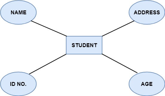
There are four types of Attributes:
- Key attribute
- Composite attribute
- Unmarried-valued attribute
- Multi-valued attribute
- Derived aspect
ane. Key attribute: Key is an attribute or collection of attributes that uniquely identifies an entity amidst the entity set. For example, the roll_number of a pupil makes him identifiable among students.
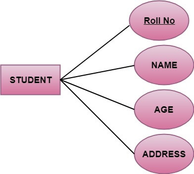
There are mainly three types of keys:
- Super key: A gear up of attributes that collectively identifies an entity in the entity set.
- Candidate key: A minimal super key is known every bit a candidate primal. An entity set may have more than one candidate key.
- Primary central: A primary key is one of the candidate keys chosen by the database designer to uniquely identify the entity set.
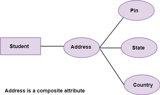
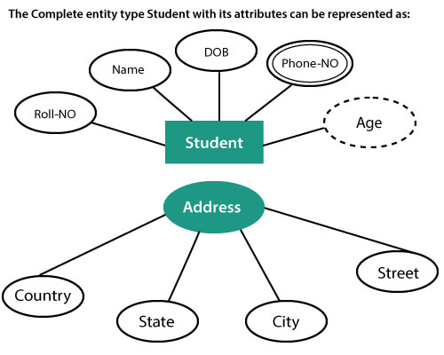
2. Composite aspect: An attribute that is a combination of other attributes is called a composite attribute. For example, In student entity, the student accost is a composite attribute as an address is equanimous of other characteristics such as pivot code, state, country.
3. Single-valued aspect: Single-valued aspect contain a single value. For case, Social_Security_Number.
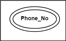
4. Multi-valued Attribute: If an attribute tin can accept more one value, it is known as a multi-valued attribute. Multi-valued attributes are depicted past the double ellipse. For example, a person can take more than i phone number, email-address, etc.
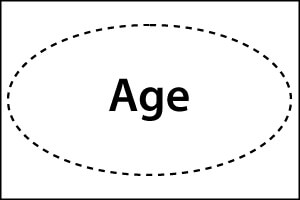
five. Derived attribute: Derived attributes are the attribute that does not exist in the physical database, but their values are derived from other attributes present in the database. For example, age can exist derived from date_of_birth. In the ER diagram, Derived attributes are depicted by the dashed ellipse.
iii. Relationships
The clan among entities is known as relationship. Relationships are represented by the diamond-shaped box. For instance, an employee works_at a section, a student enrolls in a grade. Hither, Works_at and Enrolls are called relationships.

Relationship set
A set of relationships of a like blazon is known every bit a relationship set up. Similar entities, a relationship too can take attributes. These attributes are called descriptive attributes.
Degree of a human relationship gear up
The number of participating entities in a relationship describes the caste of the relationship. The iii most mutual relationships in E-R models are:
- Unary (degree1)
- Binary (degree2)
- Ternary (degree3)
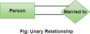
1. Unary relationship: This is also called recursive relationships. It is a relationship between the instances of i entity type. For example, one person is married to only i person.
2. Binary human relationship: Information technology is a relationship betwixt the instances of two entity types. For example, the Teacher teaches the discipline.

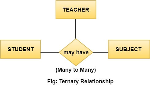
3. Ternary human relationship: It is a human relationship among instances of three entity types. In fig, the relationships "may have" provide the association of three entities, i.e., TEACHER, STUDENT, and Bailiwick. All 3 entities are many-to-many participants. There may be i or many participants in a ternary human relationship.
In general, "due north" entities can be related by the same relationship and is known as n-ary relationship.
Cardinality
Cardinality describes the number of entities in one entity set, which can be associated with the number of entities of other sets via relationship set.
Types of Cardinalities
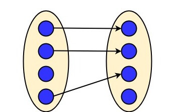
1. One to One: I entity from entity set A can be independent with at most one entity of entity prepare B and vice versa. Let u.s.a. assume that each student has only one student ID, and each student ID is assigned to only i person. And then, the relationship will be one to one.

Using Sets, it can be represented as:
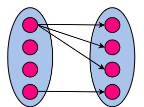
ii. 1 to many: When a single case of an entity is associated with more than i instances of another entity then information technology is chosen one to many relationships. For example, a customer can place many orders; a order cannot exist placed by many customers.

Using Sets, it can be represented as:
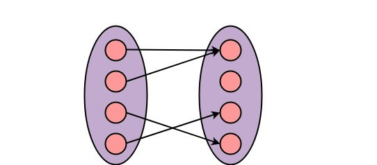
3. Many to I: More than ane entity from entity set A can exist associated with at most one entity of entity set B, however an entity from entity set B tin can exist associated with more ane entity from entity set A. For example - many students tin can study in a unmarried college, but a student cannot report in many colleges at the same time.

Using Sets, it tin can exist represented every bit:
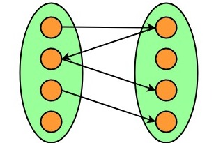
4. Many to Many: One entity from A can be associated with more than one entity from B and vice-versa. For example, the educatee tin be assigned to many projects, and a projection tin be assigned to many students.

Using Sets, it tin can be represented equally:
mcnicollknewhervel.blogspot.com
Source: https://www.javatpoint.com/software-engineering-entity-relationship-diagrams
0 Response to "Draw Entity Relationship Diagram Boxes in Java"
Post a Comment